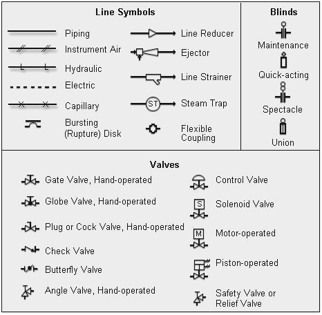
Piping diagrams are designed in a way that will be understandable for non-technical personnel. The drawings would help to speed up the fabrication and erection work at the site. These drawings are schematic representations and they would define functional relationships in a piping system. Visit our technical and career updates at our Blog site .The main purpose of a piping drawing is to communicate the information in a simple way. Vertical & horizontal rolling (with both vertical and horizontal hatch lines- 2 triangles )īasic isometric pipeline connection symbols are given below:įor more detailed trainings on QA QC courses, welding Inspections, welding courses, NDT courses, Oil & Gas Jobs and course fees details please feel free to reach us, Advanced Quality Centre, Training institute in Coimbatore, Tamilnadu, India.Horizontal rolling (with horizontal hatch lines ).Vertical rolling (with vertical hatch lines ).There are three types of rolling, the hatch lines in the right angled triangle nearby denotes the type of rolling : Rolling or otherwise called as offset gives us the exact detail of change in direction of pipeline,


Spool number are sub divisions of Line number given during fabrication to facilitate transportation of pipelines, the spools are connected on-site to complete the line. Line number is given to each individual pipe line and the number is applicable for its whole length, until it joints to another pipeline or a equipment. We shall learn from the basics, Directions:ĭirection symbol is given on top of Pipe Line Isometric drawing to determine the directions of pipelines Symbols of Pipe Line Isometric Drawings.This Blog gives a detail study of P&ID and Pipe Isometrics, with details of


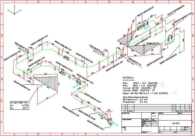
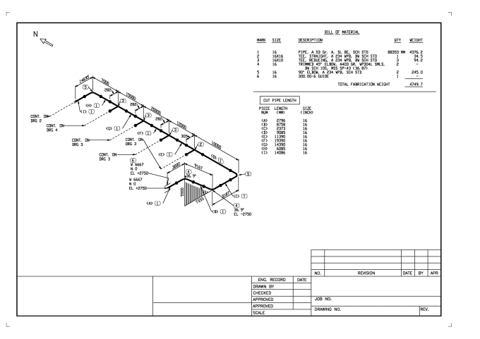
Įxample of a P & ID is given below in figure-B Figure B : Example of P & ID ( Piping and Instrumentation Drawing ) P & ID : is called as Piping and Instrumentation Drawing, is a pictorial representation of Pipeline in a single line diagram along with processing Equipments/ Instruments and storage tanks. Pipe Isometrics : Are drawings which shows details of Process pipe lines in a single line presentation, with details of pipes, pipe connections ( valves, flanges, nipples, reducers, end cap, elbow, etc), along with the dimensions and direction of pipe line.Įxample of a Pipe Line Isometric Drawings is given below in figure-A Figure A: Example of Pipe Isometric Drawing


 0 kommentar(er)
